Sync Points
Contents Hide
Sync Points are where the user can define the data flow between BrightServer and the remote clients. Each Sync Point panel is a workspace where the user can graphically layout the data flow elements, and easily visualise what data is flowing between BrightServer and the remote end-points, such as scripts, server databases or files in the system.
The simplest possible data flow is a single remote end-point connected to some type of data source, for instance, a server table and database. In the figure below, the data flow is the Menu data being sent from BrightServer to the client. The direction of the arrow heads shows the direction of the data flow.

The Database component represents the actual database that BrightServer will connect to and interact with. The remote end-point or Client Table sync point, referred to as “MENU” in the above diagram, represents a simple data object on a remote client. In this example, “MENU” represents the menu table on the client side.
The data flow as a whole represents how BrightServer is configured to expose the MENU table out from “Database1” to make its data available for remote clients to synchronise. In effect, BrightServer will read the data in MENU table on Database1, and make that data available to any remote clients that connect and request MENU data.
From this simple starting point, it becomes possible to build more and more complex topologies, describing the data flow for the project. In the figure below there is data flow in both directions from the central database, with transformation points in the process.

Using the Sync Panel
A sync panel defines a collection of sync points within a BrightServer project. Using database, file or user defined sync point data sources,to handle device synchronisation to the BrightServer instance. It is possible to fully define the data flow for any BrightServer project using one or many Sync Point workspaces, with equal effect. The number to be defined is generally dependant on how the user prefers to view the data flow, and the space available in the panel.
Ann exception to this is when dealing with files as a data source; separate sync points may need to be utilised if there are dependencies between data sources requiring group caching. Furthermore, sync rules which transmit parent and child tables must have all tables located in the same sync diagram.
To create a new sync point definition, right click on the 'Sync Points' node and select 'New Sync Point'.

This will create a new sync point panel, and open it for editing.
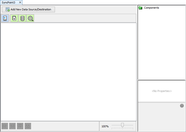
Within this sync point panel, the client table and other data accessor sync elements may be dragged and dropped from the toolbar into the panel. Once in the panel, these elements may be arranged in any position, by clicking and dragging them with the mouse. Elements can be lined up relative to one another via the grouping options at the bottom of the panel, or snap points while dragging and dropping.

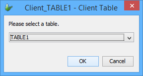
Once placed, elements' icons may be double clicked for editing; specifying database, file or script settings, or creating references to existing tables.

Data flow connectors between sync points may be established CTRL + Dragging the mouse from one sync point (the source) to another (the destination). The connector will snap to position if the point is valid, indicating success. This may be done in either direction, provided the source and destination may accept the connections in the direction dragged.

Selected elements and connections may be removed by tapping the DEL button on the keyboard. Alternatively, 'Delete' may be selected after bringing up the context menu. Removing an element will also remove all connections to the element.
Create New Data Source or Destination
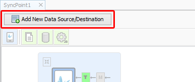
The Data Source/Destination wizard may be used to create end-to-end mappings, with any necessary data operations, for the sync point panel. This tool may be accessed by tapping on the 'Add New Data Source/Destination' button, located above the sync point toolbar.
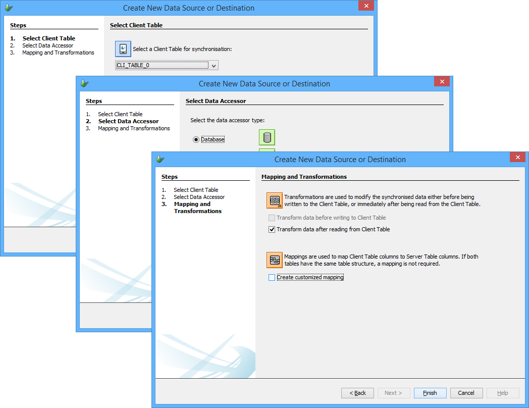
This will create end-to-end data synchronisation paths for devices to server, or vice versa, via the following steps:
Client Table, Direction
Data Accessor
Mapping and Transformations
Upon completion, the Client and Data Accessors will be present in the sync panel, connected in the direction of the synchronisation. Any mappings or transformations which were specified to be created in the wizard will also be created with default templates/values, and be assigned to the client table.
Client Tables
Client Tables represent the table data in BrightForms applications which is synchronised to or from via BrightServer. Each client table sync point is set to a BEP table via its 'Client Table' property, which may be set either using the properties panel or by double clicking the sync point. Client tables used in this manner generally mirror tables found in the application's BSP.
 Note: BEP tables may not be assigned to multiple Client Table
sync points within a single sync panel. Attempting to set a table
which has already been assigned will produce an error in the editor.
Client Table Connectivity
Within the sync points editor, Client Tables may be connected to and from database, file or script data accessors, matching the sources and direction of synchronisation of the BrightForms project.
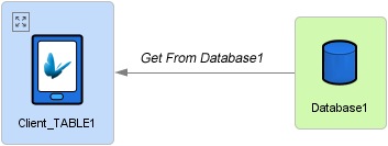
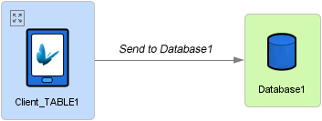
For example, any table specified for a sync rule's query would need to be present in the sync point panel. Then, if the sync rule is set as 'Server to Client' aka, 'inbound' to the device, a connector from a data source to this client table must also be defined in the panel. When executing this sync rule, if these elements are not in place, an error will occur when the device synchronises to the server.
Each table may only have one input and one output connection, but these connections may be in either or both directions, depending on the sync requirements of the project.

Data Operations
Every client table has additional properties which may be applied to the dataflow between table and accessor - Mappings and Transformations. These are operations which occur on the dataset sent to or retrieved from the device. Inbound and outbound data to the client database may be assigned a single transformation and a single mapping for a single direction. If two operations exist for a single direction, they will be performed sequentially in the order displayed, ie, such that mapping is always performed lastly to, and firstly from the server.
Data operations may be created and/or assigned by expanding
the client table with the [ ]
marker on the control, then tapping on the T(ransformation) or
M(apping) buttons in the applicable direction.
For more information on creating the definitions for these operations, please refer to the Mappings and Scripts > Transformation Scripts chapters of this document.
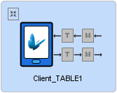
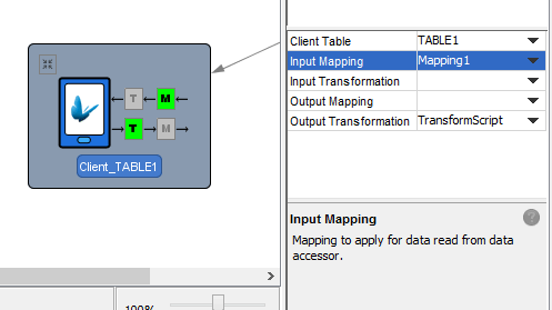
When connecting a data accessor to a client table sync point, mappings in certain directions may also be mandatory for the client table. In this situation, the panel will automatically expand on connection, and display the missing definition highlighted in red. If not mandatory, the operation will appear with a grey background, able to be tapped and assigned. Any assigned nodes for the client table will appear in green after assignment.

In addition to clicking on the 'T' and 'M' targets, assignment of these operations may alternatively be edited via the properties panel for the client table sync point.
Data Accessors
Database Data Accessor
A database data source represents a database which are connected to server tables, or may be accessed as a data source for web or online queries. It can be as simple as a Microsoft Access database or full fledged relational database such as Microsoft SQL Server, Oracle, or IBM DB2.
The figure below shows the properties on a database component, and its connectivity to client tables in the project, as well as the existence of optional mapping and transform operations.

Database Definition
The Database property of a database sync point defines how BrightServer is to connect to the data source.
The figure below shows the Database dialog, which defines the database connectivity settings for the central database in the last example. Using this dialog you can select the database type, and enter the settings for the database type selected.

If you need to connect to a database which is not listed in the database type drop down list, you can select “Custom” database type and specify the JDBC driver details. If this is the case, the JDBC database driver (JAR or ZIP) must be placed into the “lib” directory under the install directory of BrightServer.
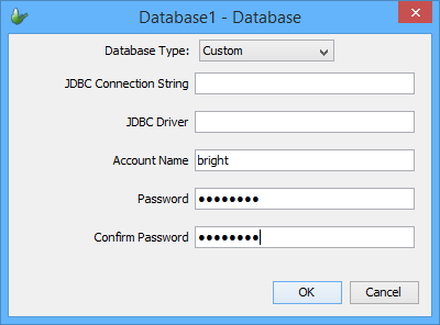
Once the Database property has been defined, BrightServer will be able to connect and work with the data source. With a database defined in an open project, the 'Database' drop down in BrightBuilder dialogs will automatically become populated with the connection values for defined sources. This is useful for BrightBuilder features such as 'Create Database Tables' and 'Import Database Tables', allowing the direct creation and importation of table definitions respectively.

Server Data Sources
If it is necessary for defined database or script sync points to act as a data source for the return of records in an online query, or access to the stored procedures of the database, the "Server Data Source" property must be set to True.

When defined as a server data source, the Database icon will change to the image as shown below.

There may be more than one server data source in a given Sync panel, and each should have their own unique ID. This ID may be set via the "Data Source ID" property. Incorrect identification will lead to validation errors.
This ID is used with the online query's 'Data Source' property, directing the query to the particular source via BrightServer. These must be detected and assigned via the project's data sources, which may be detected using the Discover Data Sources operation for a project. While open, a BrightServer BEP project's data sources may be discovered by a BSP Project using this feature.
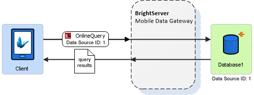
The "Default Server Data Source" property may be set true to have the sync-point be identified as the default server data source, in the case that the data source to be accessed is not specified for a particular query in a BSP Project. Only one default should be defined at a time; if more than one is defined, a validation error will occur.
If an application is to run with the server definition in BrightWeb, both a default server data source and database must be defined for the project. Any queries made in the project will query the server database as an online query. For more information, please refer to BrightWeb > Designing for BrightWeb > Data via Server Direct Access.
Database Data Operations
Connecting the database data accessor to a client table may be performed with no additional mappings or transformations specified. This will send and receive data to and from the server table, on the assumption that it exists with the same name as the client.

If the table does not exist, a server error will occur. If data to be sent to a differently named server table, mappings must be defined from the client sync point. Tapping the [M] icon on the source or destination client table will open the mappings dialog to define this configuration. This may be used to allow client tables to map to differently named and specified server tables, and vice versa. For more information regarding this dialog, please refer to the Mappings > Query Mappings section of this document.
Complex data manipulation may also optionally be carried out by BrightServer's Transform operations. These transformations will occur before sending the client table data to server tables, or before receiving data from server tables. The client table's [T] icon may be used to set or edit these transformation scripts. For more information, please refer to Scripts > Transformation Scripts.

Database Accessor Properties
Below is a table of the database accessor's available properties.

| Property | Description |
| Default Data Source | If set to 'true' online queries without a data source ID will sync to this data accessor as the target for the query. |
| Data Source ID | A number unique across sync panels in the BEP for the data source to be identified by online queries. |
| Server Data Source | Expose as a data source for online query (or BrightWeb) access. |
| Script | Parameters used to connect to the database. Tapping on the ellipsis will open a dialog for database definition. |
User Defined Sync Point
A user designed data sync point represents a JavaScript file which specifies how data is manipulated in different read/write scenarios. These scripts may be viewed, created and deleted under the 'scripts' node in a BrightServer project.
The Reader, Writer, Online and RPC scripts all require to be present in the sync panel to be recognised by BrightServer. If not a data source, they must also be connected to a client table, and allocated a mapping for each sync direction. The BrightServer > Scripts > Implementing Scripts chapter details how to implement each type of these scripts in a BEP project, and how they function with synchronisation.
To add a user defined sync point, select the user defined sync point icon from tool bar then drag and drop it into the sync panel. When connecting the script to other sync panel elements, the direction of synchronisation defined will influence what methods are expected in a user defined sync point when it is called. If they are not present, it will result in a server error. For more information regarding the utilisation of scripts, please refer to the BrightServer > Scripts chapter of this documentation.
Script Definition
The script to execute is defined via the 'script' property of the user defined sync point. The property's value may be chosen from the scripts defined in BrightBuilder (and in the scripts node) via the drop down menu. Double clicking the icon will open up the script for editing. If it does not exist, the New Script Wizard will open, which will create, assign and open a new script.

Script Server Data Sources
Scripts with the execute() or executeRPC() methods - i.e. Online and RPC scripts, must also need to be set as server data sources, achieved in the same way as databases. Please note that each script data source must have an ID which is unique across databases and user defined sync points.


Script Data Operations
Upon connection to a script data accessor, a client table will expand, and highlighting any mapping(s) which are needed. The [M] icon may then be tapped to create or assign mappings to the node. For more information regarding this dialog, please refer to the Mappings > Query Mappings section of this document.
For client to server mappings, source columns must match those retrieved from the device, with the destination columns usable by the input RecordSet vector. For server to client mappings, source columns of the mapping must match the field info specified of the RecordSet output(s) of the script. For server to client scripts, the return RecordSet name must also be equal to the client's, otherwise records will not be processed.
Each direction in and out of a script may contain at most one Mapping in each direction, and an Optional Transform may also be performed for more complex data operations. This may occur using the [T] button of the client table.
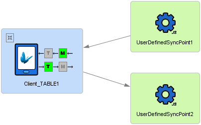
Online and RPC scripts do not require any connections, and can exist in the sync panel alone. These scripts are invoked via query definition in BSP projects, specifying the 'Data Source' property to match the script identifier in the panel. If no data source is found, the default data source in a BEP project will be used. For more information, please refer to the Queries > Online Queries section of BrightBuilder.
Script Accessor Properties
Below is a table of the script accessor's available properties.

| Property | Description |
| Default Data Source | If set to 'true' online queries without a data source ID will sync to this data accessor as the target for the query. |
| Data Source ID | A number unique across sync panels in the BEP for the data source to be identified by online queries. |
| Server Data Source | Expose as a data source for online query access. |
| Script | User defined script. Drop-down selection of all defined scripts in the BEP project. |
File Data Accessor
The other central sync source type is the File Accessor, which defines a single file for reading and writing server data. File accessors must be connected to mappings in order to interface with client tables. These mappings detail the expected format of the file when the device synchronises to the server, whether it be CSV or fixed-width.
The figure below shows an example of a configuration using the File accessor, with properties displayed. It also shows the mandatory mapping included for client tables connected to the file accessor.

The file itself is defined by the "File name" property, which may or may not be an existing file on the system. The way this file is managed may also be managed by the following file sync point properties:
The “Append” checkbox applies to files that are being written to. If ticked, then when the file is being written to, the new data is written to the end of an existing file.
The “Ignore If Not Exist” checkbox applies when files are being read. When a file is set to be read, if the file does not exist, then an error is produced by BrightServer. If this checkbox is ticked, then a non-existing file is ignored, and no error is thrown.
The “After Read, Save As” column holds a file-name for when a file has been successfully read, then the file contents are copied into the specified file-name.
 Note: Bright Software value place holders ($BV$ value markers)
can be used when specifying the file names. Those $BV$ value
markers will be substituted at run time to construct the file
names. This is the ideal method to enable users to synchronise
to and from different files. See the appendix
for more information on these value markers.
Dropbox Files
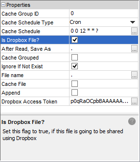
Files may be specified to be accessed via Dropbox using the 'Is Dropbox File?' property. If this is checked as true, BrightServer will use the filename specified in the 'File name' property to as the path retrieve a file on Dropbox.
Due to the nature of Dropbox, the 'File name' property for uploaded files must be unique for each transaction, as overwriting and appending files are not supported. This may be achieved by using $BV$ Value Place Holder values in the filename, for example:
\upload\Order_$BV$_DATE_;yyyyMMddHHmmss$BV$_$BV$_USER_NAME_$BV$.txt
The above file name will write the file with a timestamp and BrightServer User ID when the records are uploaded to Dropbox.
\upload\$BV$ORDER_ID$BV$.txt
The above file name will write a file based on the record's ORDER_ID field.
Authorisation to Dropbox is established via the 'Dropbox Access Token' property. This must be specified and valid in order to access the Dropbox account if synchronising by file. For more information on generating this token, please refer to the Generating Dropbox Access Token chapter of the appendix.
 If
an 'App Folder' access type application was used to generate
the token, the file path must be specified relative to the
'Apps' folder in Dropbox.
File Caching
File caching allows subsets of data to be read from a file data source. It must also be activated to allow tables represented in the file data sources to be joined using synchronisation queries.
By default when data is synchronised from a file to a client table, all the rows from the file will be sent to the client. Hence any conditions in the synchronisation query will have no effect on the data set being sent to the client.
However, if only subsets of the data on the file need to be read, then the file must be cached on the server. Data from a file will periodically be cached into server memory. This may also be performed manually via the server's Job Status panel. The cached data on the server may then be treated like a database data source. This means that complex queries, and online ones may be used to read the data on these files.
File caching is also defined by the File Accessor's properties. To enable File Caching:
Enable the Cache File property of a File data source as shown below.

Select a Cache Schedule Type. Caching is done on a scheduled basis. There are two options in this regard:
Simple - Caching performed at timed intervals in seconds.
Cron - Caching is scheduled according to a more complex timing schedule.
Depending on the Cache Schedule Type, define the Cache Schedule.
Simple - Define in seconds, how often to cache the file. For instance if you select the Simple option and enter 3600 (seconds), a job will run in one hour intervals to import the file into the internal memory database.
Cron - Refer to Cron Expressions for more detail on cron expressions. The example above is a cron schedule which will run at 12pm daily.
File Group Caching
File caching may occur such a set of files may be cached and updated within the same transaction, having any errors triggering a roll back of all the files within the set. This is used to ensure that data sets with dependencies are always maintained and kept up to date with one another.
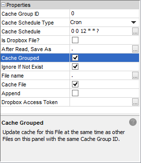
All files within the same sync point with the Cache Grouped property set to true will have this simultaneous updating take place with other file accessors containing the same Cache Group ID. Grouping may only occur within sync points, i.e. tables may not be considered as a group if they originate from different sync points in the BEP definition.
Please note, that this property must be used in conjunction with 'Cache File' property. If 'Cache File' is not set to true, an error will display on BEP validation.
File Data Operations
The file to be written for is determined by the 'File name' property of the file data accessor.
Connecting a file data accessor to a client table requires mapping to be defined in the direction of the connection, defining how data is read/written to files. This may be written formatted via CSV or fixed length formatting. Upon connection to a client table, it will expand, displaying the data operations, and highlighting and missing operations if applicable. Tapping on the [M] icon the expanded client table will open up the mappings dialog to assign or create a new mapping for the sync flow. For more information, please refer to Mappings > CSV File Mapping and Mappings > Fixed Length File Mappings.
Additionally, transformations may also be performed prior to the files being written, or after the files have been read.
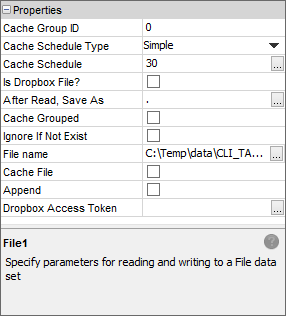
File Accessor Properties
Below is a table of the file accessor's available properties.
| Property | Description |
| Cache Group ID | Files which are to be cached in a group should have the same Cache Group ID. This is useful for having multiple groups on the same sync point panel. |
| Cache Schedule Type | Selection of 'Simple' or 'Cron'; type of the 'Cache Schedule' property. |
| Cache Schedule | Define Simple time interval (in seconds) or Cron expression for file caching. |
| Is Dropbox File? | Set this flag to true if this file is going to be shared using Dropbox. Full Dropbox path and token must be specified in File Name and Dropbox Access Token fields respectively. |
| After Read, Save As | Specifies a file name. If this element is specified, then every time this file has been successfully read, the source file is copied using the specified file name. |
Cache Grouped |
Update cache for this file at the same time as other files on this panel, if they contain the same cache group ID. |
| Ignore if Not Exist | By default, an exception is thrown when the file to be read does not exist. If set to true, and if the file is missing for this set, then the file will be ignored for reading data. |
| File Name | Contains the name of the file to be read or written to. This filename may contain the wildcard characters * and ?. The filename may contain the BrightXpress value markers ($BV$). When reading, if the filename starts with 'http', then the file will be treated as being read from a URL using http. |
| Cache File | Auto cache file data into memory. Enables parameterised queries on the file data. |
| Append | If true, then when writing to this data source, information will be appended if the file already exists. Otherwise, file will be rewritten from the beginning. |
| Dropbox Access Token | Provide the access token that is generated by Dropbox. This token will then allow BrightServer to access files using Dropbox. |
